I2C Bus
Inter Integrated Circuit bus

Philips Semiconductors
I2C-BUS SPECIFICATION VERSION 2.1 JANUARY 2000
BENEFITS DESIGNERS AND MANUFACTURERS
- In consumer electronics,
- telecommunications and
- industrial electronics,
there are often many similarities between seemingly unrelated designs.
For example, nearly every system includes:
- Some intelligent control, usually a single-chip microcontroller
- General-purpose circuits like LCD drivers, remote I/O ports, RAM, EEPROM, or data converters
- Application-oriented circuits such as digital tuning and signal processing circuits for radio and video systems, or DTMF generators for telephones with tone dialling.
To exploit these similarities to the benefit of both systems designers and equipment manufacturers, as well as to maximize hardware efficiency and circuit simplicity, Philips developed a simple bi-directional 2-wire bus for efficient inter-IC control.
This bus is called the Inter IC or I2C-bus.
At present, Philips’ IC range includes more than 150 CMOS and bipolar I2C-bus compatible types for performing functions in all three of the previously mentioned categories.
All I2C-bus compatible devices incorporate an on-chip interface which allows them to communicate directly with each other via the I2C-bus.
This design concept solves the many interfacing problems encountered when designing digital control circuits.
Features
- Only two bus lines are required;
- a serial data line (SDA) and
- a serial clock line (SCL)
- Each device connected to the bus is software addressable by a unique address
- A simple master/slave relationships exist at all times;
- Masters can operate
- as master-transmitters or
- as master-receivers
- It’s a true multi-master bus including collision detection and arbitration to prevent data corruption if two or more masters simultaneously initiate data transfer
- Serial, 8-bit oriented, bi-directional data transfers can be made at
- up to 100 kbit/s in the Standard-mode,
- up to 400 kbit/s in the Fast-mode, or
- up to 3.4 Mbit/s in the High-speed mode
- On-chip filtering rejects spikes on the bus data line to preserve data integrity
- The number of ICs that can be connected to the same bus is limited only by a maximum bus capacitance of 400 pF.
Examples of I2C-bus applications.
TV set
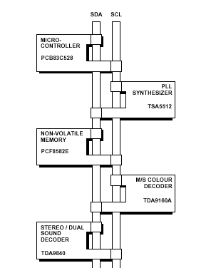
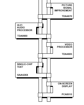
DECT Cordless phone base station

Designer benefits
I2C-bus compatible ICs allow a system design to rapidly progress directly from a functional block diagram to a prototype.
Moreover, since they ‘clip’ directly onto the I 2 C-bus without any additional external interfacing, they allow a prototype system to be modified or upgraded simply by ‘clipping’ or ‘unclipping’ ICs to or from the bus.
Here are some of the features of I2C-bus compatible ICs which are particularly attractive to designers:
- Functional blocks on the block diagram correspond with the actual ICs; designs proceed rapidly from block diagram to final schematic
- No need to design bus interfaces because the I2C-bus interface is already integrated on-chip
- Integrated addressing and data-transfer protocol allow systems to be completely software-defined
- The same IC types can often be used in many different applications
- Design-time reduces as designers quickly become familiar with the frequently used functional blocks represented by I2C-bus compatible ICs
- ICs can be added to or removed from a system without affecting any other circuits on the bus
- Fault diagnosis and debugging are simple; malfunctions can be immediately traced
- Software development time can be reduced by assembling a library of reusable software modules.
In addition to these advantages, the CMOS ICs in the I2C-bus compatible range offer designers special features which are particularly attractive for portable equipment and battery-backed systems.
They all have:
- Extremely low current consumption
- High noise immunity
- Wide supply voltage range
- Wide operating temperature range.
Terminology
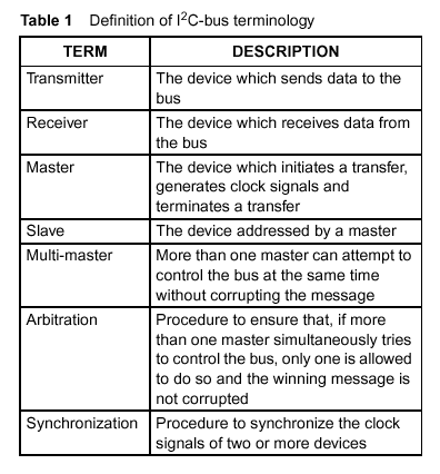
Multi-master bus
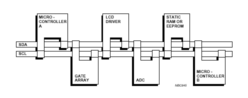
Fig.2 Example of an I 2 C-bus configuration using two microcontrollers.
Device connections
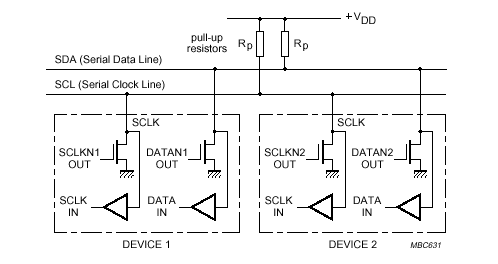
Fig.3 Connection of Standard- and Fast-mode devices to the I
2C-bus.Bit transfer
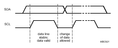
Fig.4 Bit transfer on the I
2C-bus.START and STOP conditions

Fig.5 START and STOP conditions.
Data transfer
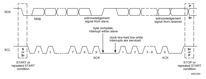
Fig.6 Data transfer on the I
2C-bus.Acknowledge
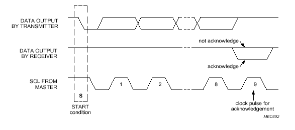
Fig.7 Acknowledge on the I
2C-bus.Clock synchronization
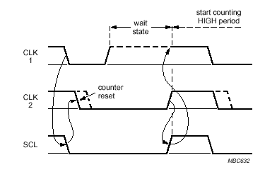
Fig.8 Clock synchronization during the arbitration procedure.
Arbitration
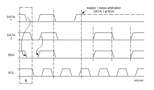
Fig.9 Arbitration procedure of two masters.
A complete data transfer
Bus signal representation
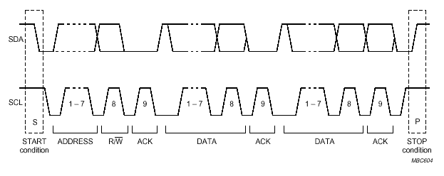
Fig.10 A complete data transfer.
Logical data representation
Read and write operations
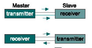
Write data
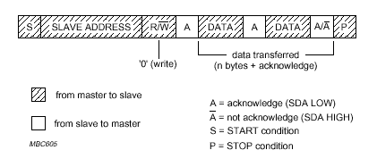
Fig.11 A master-transmitter addressing a slave receiver with a 7-bit address.
The transfer direction is not changed.
Read data

Fig.12 A master reads a slave immediately after the first byte.
EB Last updated on 10 January 2003